Why 2 lan on the motherboard. Server PCI network card with two Gigabit Ethernet ports
Greetings to all, dear readers of the blog site! In my previous articles, and specifically, I mentioned certain ports or connectors that are literally “stuffed” with any modern motherboard. So, in this article we will try to understand with you the purpose of these connectors.
Connectors on motherboards can be located both inside the computer case (we don’t see them) and outside - on the back and front of the system unit. The latter often duplicate each other for the convenience of connecting various devices. All the information that goes below is also relevant if you have a laptop, because its ports are no different from those on a regular PC.
And this is the first category of connectors, perhaps the most extensive of all. It includes a large number of connectors on the computer motherboard. If you are already familiar with the structure of a computer, then you should know that the motherboard is the most important “board” in the computer, because all other components are connected to it, such as the processor, video card, RAM and others. Therefore, all these devices have their own connectors.
CPU
The processor socket on a computer motherboard is often called a “socket” (from English - “socket”). Let's imagine that the socket is a lock, and the processor is the key to it. It turns out that for a single lock only its own key is suitable. Only in our case, several “keys” (processors) can approach the conditional “lock” at the same time. Do you know what I mean? Each socket limits the number of processors that can be installed in it. I already had a separate one, I recommend reading it.

It is easy to determine the location of the socket; it looks like a large square with many “holes” or “pins”, and is located almost in the very center of the board - closer to its top. Different processor brands use their own sockets; for example, the following types of sockets are suitable for Intel:
- Socket 1150
- Socket 1155
- Socket 1356
- Socket 1366
- Socket 2011
But processors from AMD use the following sockets:
- Socket AM3
- Socket AM3+
- Socket FM1
- Socket FM2
RAM
For RAM, the motherboard also has its own connector, or rather several. They have an oblong shape and are located slightly to the right of the processor, and their number, as a rule, does not exceed 4 pieces. At the time of writing this article, DDR3 memory is already used everywhere in the world, although DDR2 is still found in some places. You can read about all their differences.

Now, we are only interested in the fact that DDR2 and DDR3 have their own ports. And you can’t just take and install DDR2 memory into the DDR3 port, it just won’t fit there. By the way, these differences in ports are noticeable even visually. And also, when looking from above, you can notice the different colors of these connectors, for example, from 4 ports for RAM - two of them are painted in one color, and the other two are painted in a different color. This is the so-called “dual-channel” mode.
Video card
The video card also has its own connector on the motherboard. Once upon a time, the AGP interface was actively used to connect a video card, which was then successfully replaced by PCI e x16 or PCI express x16. In this case, the number 16 is the number of lines. There are also x4 and x1, but you can’t install a video card in them.

Video card connectors are located at the bottom of the motherboard, and there can be several of them, I mean PCI express x16. True, this does not happen often, only on “gaming” motherboards, and all this is needed to create SLI or Cross Fire. This is when several video cards, often no more than two, are connected to the motherboard and work in parallel, that is, their power is combined, roughly speaking.
HDD
A “SATA” cable is very often used as an interface for connecting a hard drive to the motherboard, which is connected to the corresponding connector. There are other connection options, such as: IDE and FDD, for example. FDD is no longer used; it used to be used to connect a Floppy drive into which floppy disks were inserted. But IDE in the past was the main option for connecting hard drives, until it was replaced by the SATA connector.

Nowadays, even optical disc (CD) drives are connected to the motherboard using a sat connector. There are different generations of Sata that look the same but differ in data transfer speed. Also, there are varieties of Sata connectors - “eSata”, “mSata”, which differ in design. In addition, some HDDs can be connected via a USB port, not to mention SCSI, or the no less exotic Thunderbolt.
Nutrition
On the motherboard, the power connectors are located in two places: next to the RAM (24-pin connector) and just above the processor socket (processor power - visible in the diagram at the very beginning of the article). If at least one of these connectors is not connected, the computer will not work. On old motherboards (before 2001–2002), this connector had only 20 pins, but now their number can be in the range of 24–28. This is the main power connector for motherboards.

Cooling
Without cooling, no computer can work for a long time, therefore, for effective cooling, coolers (fans) are installed in the computer, the most important of which is designed to cool the processor and is installed directly on it. To power these fans, the motherboard has special connectors with two, three or four pins:
- 2 contacts are a regular cooler;
- 3 contacts - fan with tachometer;
- 4 contacts - a cooler that uses a pulse-width converter, which allows you to change its rotation speed. The processor cooler is connected to this connector.
If desired, regular fans (without the ability to control speed) can be powered from the Molex connector of the power supply. This may be necessary if there are no free slots for coolers on the motherboard.
Additional devices
This number includes a variety of additional expansion cards: audio cards, network cards, RAID controllers, TV tuners, and so on. All of them can be connected to the motherboard via a PCI connector, but not an “express” one, but a regular one. This should also include a round-shaped connector for the CMOS battery, because of which the time on the computer is not lost every time it is turned off, just as the BIOS settings are not lost.

Pay attention to the CD IN connector plug on the motherboard; it is necessary to connect CD drives with the ability to listen to CDs and control - switching tracks forward/backward. Somewhere nearby there are pins labeled “SPDIF” sticking out - this connector can be used to connect a home theater, for example. To do this, order a special bracket with this port, which is attached to the rear wall of the system unit; the bracket is connected to the motherboard via a cable.
The SPDIF port is usually found on expensive motherboards. It is not installed on budget models, but on the board itself you can find contacts intended for connecting this port.
On the front panel of the system unit
For convenience, on the front panel of any modern (and not so modern) computer there are several USB connectors, as well as an input for connecting headphones and a microphone - the latter is usually painted pink. But, as you understand, these connectors will not work by themselves; they must be connected using wires to the motherboard. For this purpose, it provides contacts that are signed accordingly.
The same manipulations must be done with the audio outputs (group of contacts “FP Audio” or “Front Panel Audio”), as well as with the card reader - if it is installed on the front panel. A card reader is an extremely convenient device for reading memory cards and it needs to be connected using wires to the pins intended for connecting USB ports.

And on the front panel you can often find an IEEE 1394 (FireWire) port, used to connect digital devices such as photo or video cameras. And for it, the motherboard also has contacts that are labeled. In general, where to connect what and how is always written in the instructions for the motherboard, but, as you can see, it’s quite possible to figure it out yourself.
Well, that seems to be it (just kidding), there are also buttons to turn on/off the computer and LED indicators of its operation. To connect them, a special area with contacts is allocated on the motherboard, located closer to the bottom of it (next to the battery). Let me make a reservation right away: there is no single standard, so the type and location of these contacts on each motherboard may be different.

So, the computer power button (Power) and the reset button (Reset) are connected to the motherboard using the Power switch and Reset switch connectors, respectively. Using similar connectors, the computer operation indicator (Power Led) and the hard drive loading indicator (HDD Led) are connected. These connectors look like small plastic “pads” with two wires (2 “pins”), one of them is positive, the other is negative.
 Wide
Wide  Small
Small
There are two types of connection (2 types) of contact pads on the motherboard reserved for buttons and front panel indicators:
- wide connection is the most convenient option;
- small connection;
- no inscriptions at all. For example, many MSI boards do not indicate designations at all, and you can figure out the connection there only with the help of the instructions.
On the back wall of the system unit
There are many connectors on the back of the system unit, some of which completely duplicate those located on the front. Their number can be completely different, again, it all depends on the motherboard model.
PS/2
Today this connector is considered obsolete, but on many motherboards it is still present and feels good, so to speak. Used to connect a mouse or keyboard. It is noteworthy that there are adapters from USB to PS/2.

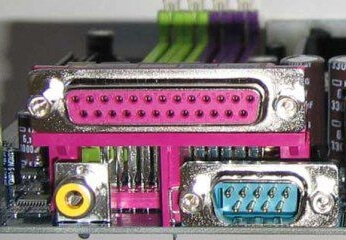
COM port
It is almost impossible to find a COM connector on modern motherboards. Previously, it was used to connect all sorts of printers and other peripheral devices, which are now connected via USB. The COM port has an analogue - LPT, which is even less common; it has an oblong shape and is painted pink.
USB ports
As a rule, if there are 4 of these connectors in front, then at the back there are at least no less. Again, everything is done so that you can connect as many devices as possible to your computer at the same time. And if the front ports are usually occupied by all kinds of flash drives, then the rear ports are often connected to “long-lasting” devices, that is, which you will not constantly connect/disconnect. Well, for example, it could be a keyboard with a mouse, as well as printers and scanners.

There are two main types of these ports:
- USB 2.0
- USB 3.0
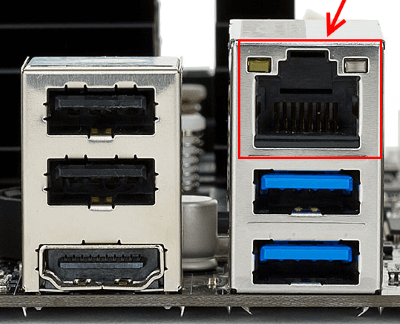
Of course, the third version is preferable due to its higher throughput; such a port is even marked with a different color - blue.
USB 2.0 and 3.0 are compatible with each other.
Network and Internet
One single connector is responsible for the network and the Internet - “Ethernet”, which is also sometimes called “RJ 45”. If you look closely, you will notice that there are small “windows” on this connector - these are indicators of network operation; when data is being transferred, they signal this. If the indicators do not light up, most likely the connector has stopped working and needs to be re-crimped (using a special crimp).
Video
Any monitor is connected to a computer (motherboard) using video connectors, which are located at the back. There are quite a few varieties of them, it would not be entirely appropriate to talk about each one here, especially since the site already has a separate article about. In my opinion, only three of them can be called the most popular video ports:
- analog VGA port
- digital DVI
- digital HDMI
The rest are not so popular and are rare.

Audio
Usually - three or six inputs for connecting several speakers and a microphone. On budget segment boards, the number of audio connectors usually does not exceed three, but at the same time, all the necessary functionality is present, and this is:
- Red - for microphone;
- Green - for speakers;
- Blue - for connecting external sources, such as a TV, player or radio.
If your motherboard has six audio outputs, then know that the other three are used to connect additional speakers and a subwoofer.

Notebook-specific
It’s worth saying a few words about rare, I would even say “exotic” connectors that are found in laptops or some other devices, but which cannot be found on a regular PC. These are two connectors: PCMCIA (ExpressCard) and Kensington Lock. The latter is used to protect the device from theft. A special cord with a lock is inserted into the “Kensington Lock” connector and tied to any object, be it a table or a battery, for example. Naturally, only you have the keys to the castle.
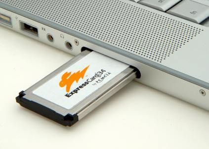 ExpressCard
  Kensington Lock
But the “ExpressCard” is a narrow slot covered with a plug into which a certain expansion card is inserted, on which ports for connecting other devices can be placed. With the help of such a card, you can easily add some USB 3.0 ports to your laptop, if only because there is a shortage of them on any laptop.
Well, that’s all, we have sorted out all the types of connectors that can only be found in a computer, if I suddenly missed something (the article is long, you understand) - write about it in the comments!
LAN - network chip on the board. It often fails and prevents the motherboard from working. One possible reason is a thunderstorm. The network chip can get very hot, which indicates its inoperability. To check, just remove it.
Gigabyte EP35-DS3 LAN problem
Good day.
Gigabyte EP35-DS3 rev board has arrived. 2.1
LAN - RTL8111B
Super I/O - IT8718F-S HXS
Symptoms -
turns on, shows the logo, if you press Del you can go into the BIOS to select settings, the next time you boot, when the final picture is shown (the second after the main one where the processor model / hard drives...) the RESET light flashes on the POST card and everything starts from the beginning.
Measures taken -
* Tested on processors - Celeron 420 65nm / Dual Core E5600 45nm
* I read the relevant topics on the forum, they write that it won’t start without a LAN.
Network repair, on Gigabyte ga-77p-d3
Good afternoon, I inherited this motherboard, everything works, but the built-in RTL8111F network interface shows no signs of life (can’t be seen in the system, the lights don’t light up), I changed the chip, all the voltages are coming to it. I have suspicions that I need to check to see if it can be turned off by signals LANWAKEB - 28th leg, and ISOLATEB - 26th leg, but I’m just a little confused about what levels should be on these legs for the network connection to work. Tell me, has anyone encountered this?
MSI A75MA-P35 strange startup
Hello everyone! The motherboard came for repair without a part with a diagnosis, it does not respond to the PW_ON button. After inspecting the board, a burnt hole was found on the sound chip, a non-working LAN and a missing part. The part was identified as a 3.3v linear stabilizer (uP0104P). Sound and the network chip removed and soldered this stabilizer and the mother began to respond to the power button and start up. After startup it works and passes the stability test. As soon as I connect any device to the power supply, either the drive, or the HDD to the molex or sata connector, the mother won't start, just jerks
ASUS M4N68T-M LE V2 no network
Hello everyone! I came across a mother ASUS M4N68T-M LE V2 with a non-working network. All network indicators are active but there is no network. There was an incorrect mac address and I decided to flash it using the DMI236 program. I enter the command and copy the mac address itself from the sticker to motherboard: A9-M0-CS-30-24-62 at the end it says that everything is OK, the firmware has become as needed. I go into Windows 7 and open AIDA 64 and go to the section: network and what I see is the mac address that I did not enter corresponds to what is written now, namely: A9-00-C0-30-24-62! I tried several times and wrote different addresses, but still two characters changed to "
Gigabyte GA-G41MT-D3V REV 1.3 network does not work
There is no network on the Gigabyte GA-G41MT-D3V REV 1.3 motherboard, but everything shows that the network is working! There is a Mac address, DHCP and DNS. I thought that the network chip was faulty and replaced it with a new one, and since the new chip did not have a mac address but only “000000000003”, I used the program to enter the required address, which was written on the sticker on the motherboard! I flashed the BIOS, the BIOS chips themselves are fine. I can’t understand, the activity indicator is blinking and the network light itself does not light up or lights up rarely, I I saw it only once, but then it didn’t light up again. It works fine on a discrete network. The board itself is otherwise working
The Gigabyte GA-P43-ES3G motherboard came in for repair, cyclic reboot! The mother starts up and the image appears, the post goes through and gives one signal about its passage and then resets and so on in a circle! I can’t enter the BIOS because when I press Del I can hear it from the speaker bangs that the keyboard reacts but does not allow into the BIOS itself! I measured the voltages, below are the results, the only thing that alarmed me was that during this reboot the voltage on the main BIOS chip on the first leg jumps! About the drop from 4.11V to 1.7V during a reset! On the PCI bus A14-3.43v A15-3.43v/On Serny Bridge 1.25v and 1.16v In the South 1.58v and 1.17v
A device such as a network card allows a laptop or computer to work on the Internet and local network via WiFi, connected via USB or via a special cable. The adapter provides a unique address called MAC, which identifies the computer device transmitting packets of information over the network. If you cannot connect with a cable, you can purchase a wireless wifi adapter for your computer equipment.
What is a network card
An element of the hardware configuration of a laptop or computer is called a Network interface controller, which provides the ability to connect to a network, ensuring interaction between devices. Network cards are LAN adapters, NICs, Ethernet adapters or interface cards. Now the Network interface controller is part of the computer package, but previously it was produced separately.
Types of network cards
An Ethernet adapter is designed to connect computer devices to a local network. The Network interface controller, which provides an Internet connection, has the main characteristic of data transfer speed. The NIC uses high-speed interfaces to interface with a computer device. There are 4 design types of computer boards. They all have basic pros and cons.
Types into which microcircuits are divided according to their physical implementation:
- integrated - as the name suggests, built into the motherboard;
- wireless – for bluetooth and WiFi networks;
- internal (separate boards) – connected via PCI, inserted into a PCI-E or ISA slot;
- External network cards for laptops are inexpensive and connect via USB.
Why do you need a network card in a computer?
The main purpose of a network card is to connect computer devices with each other. The Ethernet adapter provides connection to the Internet. If there is no built-in Network interface controller, then USB modems are used, but then the ability to work over the network is reduced. By combining computers, laptops, peripheral devices (scanners, printers, etc.) in one local network, you can exchange data via WiFi within the boundaries of an apartment, house or provider network.
Principle of operation
Some of the functionality of the Network interface controller can be transferred to the central processor or driver. Information is transmitted over the network, which is grouped into data packets. They move from one device to another. There is software and hardware involved in data transfer. NIC refers to hardware. It is responsible for establishing a physical connection between devices. An 8-pin RJ-45 or 15-pin AUI connector is used.
Where is the network card located in the computer?
The network card in the computer is located in the system unit. You can find it by slightly opening the side cover of the system unit. Modern computers are made with an Ethernet interface. The built-in NIC is soldered onto the motherboard. If it is not built-in, then it is inserted into one of the free white slots. Operation and data transfer are carried out using an optical fiber cable connected to the adapter connector.
What does a network card look like?
You can see what a network card looks like in online stores that have photos of devices. Externally, the device looks like a flash drive, and internally it is a small chip or board located near the computer network connector. It is curved on one side. If you do not open the side panel of the system unit, the location of the Network interface controller looks like a socket for connecting a cable.
How to find out your computer's network card
In the Windows operating system, it is not difficult to identify the NIC, which is necessary in case of a malfunction or when replacing. Programmers call such adapters consumables, because they tend to break. The network card for a PC is an important part of the system configuration, so you can use special programs such as “Everest” and “AIDA64” to detect it. You can determine the model name yourself by following the path:
- Start.
- Control Panel.
- System and safety.
- System.
- Device Manager.
- Network adapters.

How to check if a network card is working properly
A broken network card for a computer or a faulty Wi-Fi card will not allow you to access the Internet or local network. Problems with serviceability may be hidden in the system settings (if you have a built-in LAN adapter) or in the tightness of the cable connection (if external). You can try updating the drivers or testing. The check is carried out in the following way:
- Computer properties.
- Device Manager.
- If there are no exclamation marks next to the name of your adapter, then the equipment is detected normally. Contact your provider.
How to install a network card on a computer
Before you decide to purchase a LAN adapter, you need to make sure that the motherboard does not have its equivalent. The NIC can simply be disabled. To enable it, activation in the basic input/output system (BIOS) is required. If it really doesn’t exist, then buy a NIC at a computer store, and then install and connect the network card:
- Remove the side cover of the system unit.
- Once you have selected a free space on the motherboard, remove the blank on the back of the unit.
- Install the NIC, secure with the mounting screw.
- Connect the cable to the LAN adapter socket.
- Turn on your computer. Light diodes will flash, indicating the exchange of information with the network.
- Set up the connection: install the driver for the network card, register the server DNS (dns).

Price
The adapter will cost up to $5. The set of functions can be selected as desired (adapter with higher data transfer speed, 2 SFP ports). You can order a set of adapters through the catalog in specialized computer hardware stores or buy them in an online store (from 299 rubles). In the table below you will find the price of a network card in Moscow:
How to choose a network card for your computer
When purchasing a board, you should focus on the criteria. The brand will be the most important. Experts recommend well-known brands that last a long time. You shouldn’t skimp on technology and buy cheap ones. The right choice will ensure the functionality of the device for many years. Choosing a network card for your computer is easy if you select it in accordance with generally accepted parameters, such as:
- Well-known manufacturer. The leaders are Tp-link and Gembird. The best discrete adapters that last a long time are considered to be from Acorp and D-Link.
- Connector for connecting to a local network. According to the standard, the product must indicate 1 LAN port.
- Port type. The classic connection interface is considered PCI for computers (including the oldest models), while PCMCIA may be suitable for laptops.
- Data transfer rate. This determines how quickly the data will load. The optimal Ethernet speed parameter is considered to be 10/100 MB/Sec. There are expensive models with a high price and support for 1Gb/sec speed.
Video: how to change the network card on a computer
Found an error in the text? Select it, press Ctrl + Enter and we will fix everything!Discuss
Network card for computer
Some time ago, or to be more precise, at the end of February, a seller from one of the Aliexpress stores approached me with a request to write about his product.
In principle, it’s not difficult to write, and the device was interesting in its own way, at least at that time there was an idea about its use.
In general, if anyone is interested in reading about a fairly well-known thing, please see the cut :)
I usually choose products for review; I don’t know why the seller offered me this particular product. But I reasoned this way: such a network card could, in principle, be useful to me, why not write it. True, after that the seller offered a couple more products, but they were not interesting to me and I refused them.
By the way, the seller has a lot of different network cards, which may come in handy.
The title of the review indicates that the network card has a PCI interface. Yes, that’s exactly it, no letters are missing at the end, this is an old standard card, now such connectors are almost never installed on motherboards.
Initially, it was taken for a motherboard with only one connector and it was PCI, so everything is correct. But I will write about the purpose of the order and why I did not apply it at the very end, but for now I will do what I promised to the seller, I will tell you about his product.
The board came in a box with the name of a company unknown to me, and this inscription was everywhere, on the packaging, on the instructions, even on the tape. 
The kit is simple, although I can’t even imagine what else could be included with a network card.
1. Network adapter
2. Bar for installation in low-profile housings.
3. Instructions
4. CD with drivers
5. Packaging. 
The instructions are nothing special, but the plank is a useful thing; I sometimes assemble computers in low cases. 
The network card is also low-profile, but quite long. Although, as for me, it could easily be shortened by 20 percent.
The board has a PCI x32 connector and looks very neat. I would like to write - as a branded card, but the fact is that I am 99% sure that this is a branded card, perhaps Intel, perhaps Compaq, but it’s branded, that’s a fact.
Most likely there are large reserves of these cards, so they are slowly selling them out. 
The board arrived in excellent condition, I will not say that it is new, perhaps well washed, but it may well be new. 
As stated, the card has two Ethernet ports. 
A closer look at the board markings. Small abrasions are already visible here, and there is also a manufacturer’s marking “Mic”, but I don’t know such a marking. 
The board is assembled on the basis of a chip, judging by the description it is a Dual Port Gigabit Ethernet Controller.
But also, judging by the description, it can work with PCI/PCI-X buses, in this case we have a simple option - PCI
I didn’t see the point in removing the radiator, firstly, I know what’s underneath it, and secondly, it’s glued well. 
A few photos of the components installed on the board.
Since the board has the ability to boot a computer over a network (PXE), there is a flash memory chip - 39F020, capacity 2Mbit (256KB). 
There is nothing more to inspect on the board, let's move on to the tests.
Testing took place on a computer with Windows 7 pro x64 OS, Core™2 Duo E4500 processor, 4GB RAM, Foxconn P9657AA-8KS2H motherboard.
Windows recognized the adapter automatically; there was no need to install anything. 
True, the driver was produced in 2008. In addition, I would not say that the driver has many settings, usually there are more. 
Here I remembered that the kit included a CD with drivers.
Everything would be fine, but finding the right one is not as easy as it seems at first glance. In the end, I simply launched a driver update, pointing to this disk, Windows itself found something there, I didn’t even understand where, and installed it. 
The picture got better, there were drivers from May 2008, and the ones from September 2008 :)
There are a little more settings. 
There is nothing to do, we go to the manufacturer’s website (Intel) and download the latest one, dated 2016 O_O 
As it turned out, the driver version remained the same, but the add-on for Intel network cards “latched on” and everything that this network card can do became available.
I won’t say that I understand at least half of what this card can do, but it’s always more pleasant when there are more settings.
By the way, booting via PXE/RPL is supported independently for each port; at least there are two PXE items when booting the computer.
For those who don’t know what it is, I’ll explain how I understand it. The computer can boot from a hard drive/CD/flash drive. But if you install a server on the network on which network loading is configured, then the computer may not have a hard drive at all, everything will happen over the network.
The screenshot is clickable. 
But here I will make a small disclaimer.
The fact is that the card chip can work with PCI 33MHz and 66MHz buses.
I couldn't find information about what frequency the PCI bus operates at on my motherboard, and this is very important for the test.
The 33MHz bus has a maximum throughput of 133MB/sec, and the 66MHz bus has twice as much bandwidth. And this speed is indicated without taking into account bus overhead, i.e. actually closer to 100MB/sec. It turns out that with a 33 MHz bus, the card, in principle, will not be able to provide more than one gigabit to both ports. 
To test it, I made a 1GB RAM disk on my computer (they didn’t give me more in the free version). After that, I connected it directly to another computer that has a gigabit network card on board and connected the RAM disk as a network drive.
Why didn't I use a more correct Iperf? The fact is that just such a mode was planned - a network drive, which is why I tested it as a drive.
1. RAM disk speed.
2. Speed of working with a network drive. 
Even out of curiosity, I ran this test, I don’t think it’s very useful, I was rather just curious. 
I have already carried out the following tests from a computer on which the card under review is installed.
Speed of access to the computer from which I conducted the previous test, working with a shared folder connected as a network drive. Here I did not create a RAM disk, since the computer has an SSD installed.
By the way, it is noticeable that the upload and reception speeds are different, and when testing from a second computer, the speeds swapped places. 
And then I checked the work with both network ports.
The scheme was like this:
The test was carried out from a computer on which a dual-port card was installed.
The first computer was connected via USB 3/0 - GbLan adapter, the test was carried out with a computer hard drive
The second computer was connected directly to the on-board network card.
At first glance, it seems that the total speed is good, but if you look closely at the load on network cards, you can see that the total load is about 96%.
This was true during the test; sometimes the load on one of the ports increased to 0-80%, but the amount never exceeded 100%.
This means that the network card chip has hit the limit of the PCI bus and 2 full ports at the same time will never work with this motherboard. 
Next, I checked the operation of each card separately.
When directly connected to the built-in card of an auxiliary computer, the network card load reached 96% without problems, while providing data transfer speeds of up to 111MB/sec. 
When using the USB 3/0 - GbLan adapter, the peak speed was the same, even a little higher, but the graph was more “ragged”.
You can say that along the way I tested the USB 3.0 adapter :) 
At the very beginning I wrote that I planned to use this card. I once reviewed my mini “server”. This is where I planned to install this network card. True, now there is another motherboard there, or rather the one that was there before, Intel GLY2, but it doesn’t matter.
I did not install the board for two reasons.
1. The board did not fit in height, although this is a solvable problem, you can place the board horizontally.
2. While I received the order, while the network was waiting for a review, my plans changed noticeably and the point of installing the card in this computer disappeared.
In general, the application did not work out, it will most likely lie on the table, just as a memory, or maybe I will use it somewhere. 
In general, I love all sorts of beautiful “things”. At the top left is a board that served in my computer for a long time until a thunderstorm killed it.
The second board also worked for a long time, but in the end I needed free slots and I switched to the built-in network card, and I didn’t notice the difference :) 
This time I will not describe the pros and cons, but will simply express my opinion.
I won’t scold this network card, it works fine, the workmanship is excellent, but to put it mildly, it’s a little outdated.
The downside is the old PCI interface, with which it can work at full speed only if the bus operates at a frequency of 66 MHz, but usually the frequency is 33 MHz and you will not get a total of more than 1 Gbit. Built-in network cards now provide operating speeds no worse than those observed.
In general, the card itself is normal, but if you need it, then I think it’s better and easier to look for it on Avito or OLKH, they probably exist there.
While I was looking for my first 3COM, I came across all sorts of hardware for the PCI bus, maybe someone will be interested :)
A moment of history
1.2. Cool 3COM network card, made in the USA, cost a lot of money :)
3.4. Intel network card, but made by Compaq. It worked great, no worse than the previous one.
By the way, it’s interesting that cheap Chinese cards often provided greater “penetration” than branded ones. They said that this was due to the fact that in the Chinese no one paid attention to power, since no one was going to certify them. 
1.2. In general, this one can already be classified as a rarity; it was bought in the ISS store, which has been gone for a long time :(
3.4. And this is a Trident video card. It lies like a spare, I think it will outlive everyone :))) 
Video capture cards for video surveillance systems. My acquaintance with surveillance systems began with the first board about 10-15 years ago. The payment is “still the same”, you can’t look at it without tears.
The second board was already better, but still “software” and with its own cockroaches, but it could work in real time 4 channels or 16 channels, but with 5 frames per second. 
Well, I think many people know this beauty, with its help they not only watched movies, but also “fished” :) 
What interesting things do you have in your stash?
The product was provided for writing a review by the store. The review was published in accordance with clause 18 of the Site Rules.
I'm planning to buy +6 Add to favorites I liked the review +35 +55Previously, people didn’t think much about the speed of cable connections in their home network. They have always provided sufficient speed and reliability, which in any case has been proven by their use millions of times. However, these days technology has reached its limits: an increasing number of computers are equipped with solid-state drives, the speed of which is at least five times higher than 1 Gbps. And the new 802.11 “ac” and “ad” wireless network standards significantly exceed gigabit Ethernet speeds.
Of course, there are cable technologies that provide speeds up to 10 Gbps, but they are intended for professional data centers and are quite expensive. But there is another possibility to provide higher speed. It consists of combining several gigabit networks. In such a scheme, the so-called “link aggregation”, two conventional gigabit LAN cables are connected and thus provide excellent integration into the existing network. However, there are some obstacles to implementing the simple principle of “2 x 1 Gbit = 2 Gbit” in practice, which we discovered during our tests.
Channel aggregation: network switches from RUB 2,500
The main element for link aggregation is the network switch, which must support this function. In most home networks, there is only a switch built into the router - these are its LAN ports. Often they cannot connect to each other.
This opportunity is provided only by modern top-class routers, such as ASUS RT-AC5300 or Netgear Nighthawk X10 (each price starts from 20,000 rubles). However, for just 2,500 rubles, LAN switches with 8 ports and link aggregation capabilities are available (for example, TP-Link TL-SG108E or Netgear Gs108E), which can be switched between the router and devices connected to the network (see diagram on the right).
Fundamental feature: the switch must be managed (that is, a web interface is required to configure it, and the firmware installed in it must provide the ability to connect ports). An indication of this is one of the terms “Link Aggregation”, “Port Trunking”, “LACP” or “802.3ad” in the datasheet.
 Computers or devices that must connect at speeds of several Gbps must have an appropriate number of LAN ports, as well as the ability to be configured at the software level. We tested two scenarios using the Netgear GS110TP switch. In the first, the NAS is connected to the switch via two LAN ports, so each of the two PCs can download data from the NAS at full gigabit speed.
This option is a targeted application of link aggregation and works relatively seamlessly. In the second option, we configured the PC with two LAN ports so that data could be downloaded from the NAS at a speed of 2 Gbps. This rather complex method involves very specific types of data transfer and often (but not always) provides double the speed.
Switch structure and configuration
In any case, you first need to start the switch: it is connected to the electrical network through its own power supply; one of its ports connects to the router (we used the last port number 8). In about a minute, it will boot, its LAN ports will work, and the web interface will become available to all computers connected to the switch (or router) via a cable or wireless network.
The switch's IP address can be found in your router's settings, and the preset password is listed in the user manual. First of all, you need to search for updates on the manufacturer’s website; For our Netgear switch, we needed to download new firmware from the “Maintenance | Download | HTTP File Download".
 The web interface of the Netgear switch allows you to configure link aggregation groups, as well as connected ports
 Link aggregation can be configured before connecting the corresponding devices. In the Netgear switch web interface, in the “Switching | LAG" click on the "LAG1" (link aggregation group) item and check the "PORT" box next to the port numbers that you want to use. Each group is used to connect one device: in the diagram on the top right, LAG1 is a NAS storage connected to ports 1 and 2, LAG2 is a PC on ports 5 and 6. In the “LAG Configuration” section, we left the default settings, we just changed parameter "LAG Type" to "LACP".
The speed of ports that do not belong to any group remains at the usual level of 1 Gbit (in the diagram these are 3, 4 and 8). Connect devices according to LAG identification. At first, only a simple cable connection to the physical first interface of the end device is active; Link aggregation also needs to be enabled on end devices. Read on to find out how to do this.
Configuring the NAS for Dual Link Mode
For our tests, we used the QNAP TS-231P, which is equipped with two LAN ports and provides high throughput. We measured FTP transfer speeds with both the NAS drive and the target PC using fast SATA SSD drives. Network settings in the QNAP web interface are located in the Control Panel | System Settings | Net".
Here in the Interfaces section both Ethernet ports are shown. Click the Port Grouping | Add" and check the box for each interface. The only mode that worked reliably with the Netgear switch during testing and produced the required results was “Balance-rr,” which uses both cables alternately to transfer data.
 After clicking the Apply button, the NAS drive will briefly go offline to apply the new settings. If you set a mode that is not supported, the NAS will not be accessible; in this case, you must press and hold the button on the back of the device for 3 seconds. This will reset your password and return your network settings to default.
In theory, basic link aggregation using two computers connected to simple Netgear switch ports should allow two files to be downloaded simultaneously from a NAS drive at 1 Gbps each. But downloading and uploading from two PCs throws the system a little out of rhythm: when downloading to a network drive, the speed is about 25% lower than the maximum theoretically possible.
Since this configuration is relatively affordable and easy to implement, it is certainly suitable for home networks in which the NAS drive is accessed from multiple computers. However, it is worth paying attention to the following: while parallel data transfer helps to exhaust the capabilities of both network lines, it also places increased demands on the drives installed in the NAS device. It is advisable to use SSD drives.
Double the data transfer speed from the NAS server to the PC is also possible, but in practice this option is quite complicated, as we found out below.
Setting up link aggregation on a PC
What can be done on a NAS drive with a couple of clicks should be just as easy to do on a PC. At least that's what they think. From a hardware standpoint, there are numerous motherboards with two LAN ports, or motherboards with the ability to install a second 1 Gbps network card for little money. From a software perspective, this becomes more complicated: this feature was originally supported in Windows 10. But after the update in the fall of 2015, utilities for this, although they exist, no longer work. This also applies to Intel network drivers, with which link aggregation can be configured in an alternative way.
Therefore, we installed Ubuntu OS on a gaming PC with a Skylake processor and two network connectors, which can be configured with aggregation, called “Port Trunking” in the Linux world. To do this, we first deactivated the Ubuntu network manager and then configured port aggregation using the Linux configuration file (“/etc/network/interfaces”). In truth, we tried various options from the Internet until the technology worked on our test PC, since the documentation on the topic is quite sparse and often contradictory.
 Our successful combination consists of four interface definitions, each of which begins with “auto...”: It first specifies a system-critical loopback device that cannot be changed. In this case, both physical LAN ports are detected, but not activated. This only occurs in the "bond0" definition of the specified link aggregation interface. Most entries are intended for configuring IP settings manually; the connection mode is indicated using the “bond-mode” line. Mode 4 is designed for connections using the 802.3ad standard and provides a maximum speed of up to 1628 Mbit/s.
Alternatively, mode 0 (“Balance-rr” works, that is, the same mode as in the NAS drive), but only at a speed of 1202 Mbit/s. For comparison: the data transfer speed on a separate gigabit line is 912 Mbit/s. Fault tolerance is a positive side effect: during data transfer, you can disconnect one of the two connectors - the connection is not interrupted, only the speed is halved.
However, there is at least one catch: both lines are only used if two files are transferred at the same time via FTP (in the Filezilla settings menu: "Transfers | Maximum simultaneous transfers: 2"). As this value increases, the speed decreases very quickly. In addition, it is necessary to pay attention to the fact that there is no other connection between the PC and the NAS server (for example, an open NAS web interface, an SSH connection), since even minimal line load leads to the fact that both data transfers are carried out only one line instead of two.
An additional disappointment: speeds during experiments with the SMB protocol, which Windows uses for remote file access, were significantly slower than over a single gigabit line. All this demonstrates that it is unlikely that the link aggregation mode in Windows could function quickly and without problems, since the Microsoft system retains control and other connections.
Our conclusion regarding link aggregation is that the process is well suited for efficiently connecting a NAS server to multiple Gigabit clients. As a fast NAS to client connection, it is labor intensive and has many pitfalls. This would require fundamentally faster network technology.
 SFP+ as the new 10-Gigabit standard
The Netgear Nighthawk X10 router is equipped with an SFP+ interface, so you can connect a device with a data transfer rate of 10 Gbps to it. Its two gigabit LAN ports are combined using link aggregation.
Ethernet 10 Gbit and SFP+
In the professional field, the 10-Gigabit standard has formed the basis of infrastructure in data centers for more than ten years. A copper option called "10GBase-T" relies on the same RJ-45 connectors as Gigabit LAN, but requires shielded (at least Cat. 6) cables and expensive hardware: a network card, for example. , Intel X540-T1 costs about 22,000 rubles, the cheapest switch with two 10GBase-T ports (ASUS XG-U2008) is about the same. NAS drives supporting this standard cost from RUB 50,000.
 Professional card
Thanks to the HP NC523SFP network card, the computer is additionally equipped with two SFP+ interfaces
The SFP+ standard is more accessible. It describes a compact modular transceiver device used in cable networks and is designed for both copper and much more expensive fiber optic cables. Both options provide data transfer at a speed of 10 Gbit/s: copper cables over a distance of 50-100 meters, fiber optics up to several kilometers. The Netgear Nighthawk X10 router has one SFP+ port. Using the SFP+ Direct Attach Copper Cable module (about 2,500 rubles), you can connect a NAS drive to it.
The cheapest SFP+ model is QNAP TS-531X-2G (from RUB 48,000). PCIe network cards that support SFP+ are available at prices starting from RUB 15,000. (Warning: Most of them only work with Windows server drivers!) However, as the Netgear router shows, the situation is emerging that SFP+ can penetrate the mass market and “blow up” the gigabit boundary.
PHOTO: Manufacturing companies; CHIP Studios
 (1 ratings, on average: 5,00 out of 5)

